Single-channel Photon Counting Software
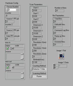
These routines configure the two 6025E counters as
follows; one counter is configured as a buffered event counter, and counts the
APD pulses from the selected APD. The counter increments until it receives a
pulse on its "gate". The value is read to a buffer and the cycle
continues until the buffer is full. The gate pulses come from the 2nd counter,
which is configured as a pulse train generator. The pulse spacing is determined
by your selection of bin time and the internal clock on the 6025E. Finally, the
buffer size is the number of bins (pixels) in a line, calculated from the X
distance, the X resolution, plus any additional pixels deemed necessary from
offset analysis. This gives the counts per pixel on a line. Download
Routines
One limitation of this software is that only one detector (A or B), but not both at the same time can be used for counting. There are only 2 counters on the 6025E, and one is used as the bin time clock while the other is the photon counter. To count both channels with this board, an alternative bin timing source is needed. We use a custom external timer as our source (although the board’s “FREQ_OUT” pin may be a suitable choice for some applications). A better choice for multiple channel acquisition is the 660X series of boards.
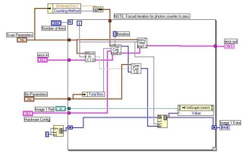
Below
is a screenshot of a simple scanning algorithm using the single channel photon
counting routine (the “Phot Cntr Mod1c” box in the diagram). The program first
executes the stage X-axis move command, then starts photon count acquisition.
An offset correction algorithm is run on the line’s data (the "Line
Correction" VI in the diagram screenshot), and the stage is then moved up
to the next line for another round of acquisition.
There
is a certain amount of delay before the stage moves, due to the RS-232
communication via the operating system. This is reasonably constant and
independent of stage velocity setting. There is also a more complex
velocity-dependent offset due to stage ramp-up time that is negligible below around
20 to 50 microns/second. These offsets require extra photon bins (pixels) to be
acquired and later deleted from the line data. We measure these offsets by
photobleaching lines in a uniform sample of surface-attached fluorophors
(BSA-Biotin plus Streptavidin-CY3) using a manual mode of stage control. Then scans
are acquired at different stage velocities and deviations from the true
positions are measured. Stage controller interface options/upgrades are now
available from Polytec PI that allow
for much higher positioning accuracy than attainable with this algorithm.